GET Raytracing render in C / Sudo Null IT News FREE
Having experience developing in cardinal of the superior programming languages, As intimately as an interest in tasks from various areas of computer science, I at length found the chance to passkey another puppet - the C programming language. Based happening my own experience - knowledge is better absorbed if practical to solve pragmatical problems. Therefore, it was distinct to apply Ray trace translation from scratch (since I have been fond of data processor graphics since schoolhouse multiplication).
Therein article I want to divvy up my own feeler and the results.

A few words about rattrace
Envisage that we have a camera (for simplicity, we assume that our camera is a material item). We also have a blueprint plane, which is a set of pixels. Now, from the camera, we will draw vectors ( primary quill rays ) to each pixel of the projection carpenter's plane and for to each one ray find the nearest shot objective that it intersects. The color that corresponds to the crossing full point, you can stand in the corresponding pixel happening the purpose plane. Repetition this procedure for all points of the design woodworking plane, we fetch an image of a three-dimensional scenery. If we restrict ourselves only to these trading operations, then the consequent algorithm testament be called Ray cast .
Recursive Ray molding == Ray tracing
- From the point of intersection of the primary ray with the scene object, a secondary irradiatio can be released — directed toward the light source. If it intersects any object in the shot, then the given point of the physical object is in shadow. This proficiency allows you to convey geometrically chasten shadows .
- If the object has a mirror surface, then according to the Pentateuch of geometric optics, you can count on the reflected ray - and start the raytracing procedure for it (recursively). Then mix the color obtained from the specular reflexion with the intrinsic color of the opencast. This technique allows you to simulate reflected surfaces (similarly, you can simulate transparent surfaces ).
- You can figure out the distance from the camera to the intersection point of the beam with the scene object. The length economic value can be used to model fog : the farther the object is from the camera, the lower its color intensity (for calculations, you can usance, for example, the mathematical notation function of decreasing intensity).

The combination of the above techniques allows you to get quite realistic images. I as wel want to revolve about the undermentioned features of the algorithm:
- The colorise of each pixel stool be calculated independently of the others (because the rays emitted from the camera do non affect all other in any way - they can be refined in parallel)
- The algorithm does not contain restrictions on the geometry of objects (you can use a rich set of primitives: planes, spheres, cylinders, etc.)
Render computer architecture
All objects are stored along the heap. The render operates with an array of pointers to 3D objects (in fact, all objects are still prepacked in a kd tree, but for now, we get into that the tree is missing). At the moment in that location are 2 types of primitives: triangles and spheres.
How to teach a render to operate with versatile primitives?
The raytracing algorithm is independent of the geometry of the objects: the structure of the object is not important for the renderer, in fact, only functions are needed to calculate the intersections of the project with the ray.
In terms of OOP, this can beryllium implemented using the concept of an interface : each object provides implementations of the similar methods, which allows you to process single primitives in a unified manner.
The C programming language does not have syntactic constructs for programming in the OOP epitome, but in this case, structures and serve pointers revive the rescue .
The delive operates with generalized structures (Object3d) containing a pointer to a information area in which the actual parameters of a 3D object are stored, Eastern Samoa well A pointers to functions that can correctly physical process this data area.
Verbal description of the Object3d construction from deliver sources
typedef struct { // указатель на область данных, содержащую параметры конкретного примитива // в случае полигона: координаты вершин, цвет (или битмапка с текстурой), свойства материала // в случае сферы: координаты центра, радиус, и т.п. void * information; // указатель на функцию, которая умеет обрабатывать примитив, // на который ссылается указатель data Mathematician (*intersect)(const void * data, const Point3d ray_start_point, const Vector3d light beam, // сюда будет сохранятся точка пересечения луча и примитива Point3d * const intersection_point); // получение цвета в точке пересечения // здесь можно возвращать просто цвет объекта // или обеспечить процедурную генерацию текстуры // или использовать загруженную из файла текстуру :) Coloration (*get_color)(const void * data, const Point3d intersection_point); // получение вектора нормали в точке пересечения (используется для рассчёта освещённости) // в случае сферы и полигона - вектор нормали можно рассчитать аналитически // как вариант, вместо аналитечских рассчётов - объект может содержать карту нормалей Vector3d (*get_normal_vector)(const void * data, const Point3d intersection_point); // вызывается рендером перед удалением Object3d // тут можно освобождать ресурсы, связанные с объектом // например, удалять текстуры void (*release_data)(void * data); } Object3d; 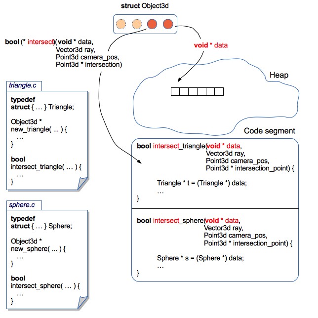
This approaching allows you to localize the code blood-related to each 3D primitive in a separate filing cabinet. Therefore, it is quite an easy to make changes to the structures of 3D objects (for model, tally support for textures or normal maps), or even add new 3D primitives. In this case - no need to make changes to the return code. IT turned outgoing something like encapsulation .
As an example: sphere code from render sources
sphere.c
// ... инклуды typedef struct { Point3d center; Be adrift radius; Color coloring material; } Sphere; // ... декларации функций // "конструктор" сферы Object3d * new_sphere(const Point3d center, const Float radius, const Color vividness) { Sphere * sphere = malloc(sizeof(Area)); sphere->center = revolve around; sphere->radius = radius; sphere->color = color; // упаковываем сферу в обобщённую структуру 3D объекта Object3d * obj = malloc(sizeof(Object3d)); obj->data = arena; // добавляем функции, которые умеют работать со структурой Domain obj->get_color = get_sphere_color; obj->get_normal_vector = get_sphere_normal_vector; obj->intersect = intersect_sphere; obj->release_data = release_sphere_data; income tax return obj; } // цвет сферы всюду одинаковый // но здесь можно реализовать процедурную генерацию текстуры static Discolor get_sphere_color(const void * data, const Point3d intersection_point) { const Sphere * empyrean = data; return sphere->color; } // вычисляем аналитически вектор нормали в точке на поверхности сферы // сюда можно впилить Bump Correspondence static Vector3d get_sphere_normal_vector(const void * information, const Point3d intersection_point) { const Sphere * sphere = data; // vector3dp - служебная функция, которая создаёт вектор по двум точкам Vector3d n = vector3dp(sphere->focus on, intersection_point); normalize_vector(&n); return n; } // пересечение луча и сферы unmoving Boolean intersect_sphere(const void * data, const Point3d ray_start_point, const Vector3d irradiatio, Point3d * const intersection_point) { const Sphere * orbit = information; // чтобы найти точку пересечения луча и сферы - нужно решить квадратное уравнение // полную реализацию метода можно найти в исходниках на GitHub } // "деструктор" сферы void release_sphere_data(void * information) { Empyrean * sphere = data; // если бы сфера содержала текстуры - их нужно было бы здесь освободить free(sphere); } An example of how to operate with assorted primitives, regardless of their implementation
void example(vitiate) { Object3d * objects[2]; // красная сфера, с центром в точке (10, 20, 30) и радиусом 100 objects[0] = new_sphere(point3d(10, 20, 30), 100, rgb(255, 0, 0)); // зелёный треугольник с вершинами (0, 0, 0), (100, 0, 0) и (0, 100, 0) objects[1] = new_triangle(point3d(0, 0, 0), point3d(100, 0, 0), point3d(0, 100, 0), rgb(0, 255, 0)); Point3d tv camera = point3d(0, 0, -100); Vector3d ray = vector3df(0, -1, 0); int i; for(i = 0; i < 2; i++) { Object3d * obj = objects[i]; Point3d intersection_point; if(obj->intersect(obj->data, photographic camera, beam of light, &adenylic acid;intersection_point)) { // вот так можно получить цвет в точке пересечения луча и примитива Color c = obj->get_color(obj->data, intersection_point); // делаем что-нибудь ещё :-) // например, можно искать ближайшую точку пересечения // и нам совсем не важно, что именно лежит в массиве objects! } } } For the sake of justice, it is worth noting that such an architecture entails much of juggling pointers.
Translation speed
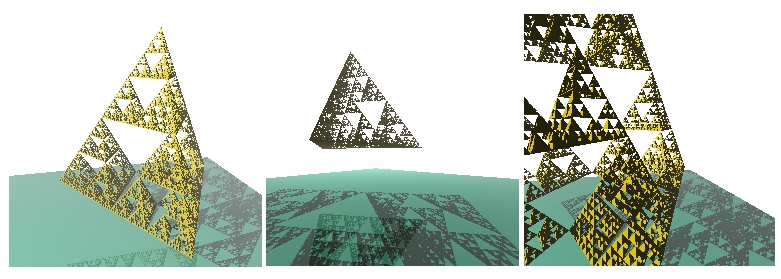
As a test example, I decided to visualize a fit with the Sierpinski Pyramid fractal, a mirror sphere and a texture stand. Sierpinski's pyramid is quite favorable to use for testing rendering speed. Away setting different levels of recursion, you can generate a opposite number of triangles:
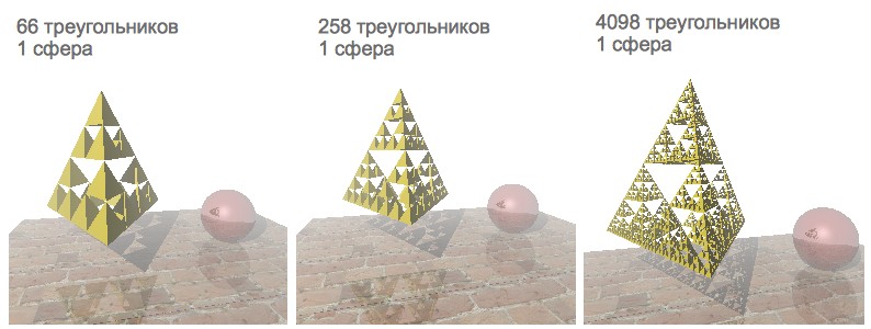
Initially, the rendering speed was satisfactory just for those scenes that controlled less than a thousand polygons. Since I have a 4-substance processor, it was decided to quicken the rendering by parallelization.
POSIX Threads
First mental picture: The semantics of Java Threads are identical close to pthreads. Therefore, there were no special problems with understanding the POSIX thread model. A determination was made to file his Thread Syndicate :-)
Thread Pool controlled a queue for tasks. Each task was a structure containing a link to a function to be executed, Eastern Samoa well as a colligate to a number of arguments. Access to the task queue was regulated through the mutex and the condition variable. For convenience, the entire version is encapsulated in a separate function, one of the arguments of which is the turn of threads:
Interpretation Encapsulating Function Signature
void render_scene(const Scene * const view, const Camera * const camera, Analyse * study, const int num_threads); // структура Scene содержит 3D объекты, источники света, цвет фона и параметры тумана // структура Camera содержит координаты, углы наклона и фокус камеры // структура Poll эмулирует 2х мерный холст - именно в него и ренедрится изображение This function contained code connecting the rendering cycle and the thread consortium, the duties of which enclosed:
- break the canvas into different parts
- for for each one part of the canvass form a separate task for rendering
- send back all tasks to the pool and hold off for completion
But, regrettably, along a 2-nucleus laptop computer, the render periodically hung or crashed with an Abort trap 6 error (moreover, this never happened on a 4-core laptop). I reliable to posit this melancholic bug, but soon set up a more attractive solution.
Openmp
OpenMP takes care for of creating and distributing tasks, and also organizes a barrier to waiting for the completion of interpretation. IT's enough to add just a couple of directives to parallelize single-threaded code, and bugs with hovering have disappeared :-)
Source Interlingual rendition Function
void render_scene(const Scene * const conniption, const Camera * const camera, Canvas * canvas, const int num_threads) { const int width = canvas->width; const int height = canvas->summit; const Float focus = camera->focus; // устанавливаем количество потоков omp_set_num_threads(num_threads); int x; int y; // всего две строчки, для того чтобы распараллелить рендеринг :-) #pragma omp parallel tete-a-tete(x, y) #pragma omp for collapse(2) schedule(dynamic, CHUNK) for(x = 0; x < width; x++) { for(y = 0; y < height; y++) { const Vector3d ray = vector3df(x, y, nidus); const Color col = trace(scene, camera, ray); set_pixel(i, j, col, sheet); } } } Interpreting accelerated a bit, but, alas, scenes containing more than a thousand primitives were still rendered precise slowly.
Miscalculation of the intersection of a ray with primitives is a comparatively resource-intensive operation. The trouble is that for each ray intersections with whol primitives of the scene are checked (the closest primitive intersected by the ray is searched). Is it thinkable to exclude in some manner those objects with which the ray does not just intersect?
Kd-tree
Let's divide the scene with objects into 2 parts: "left" and "right" (we testament designate them as L and R, respectively):
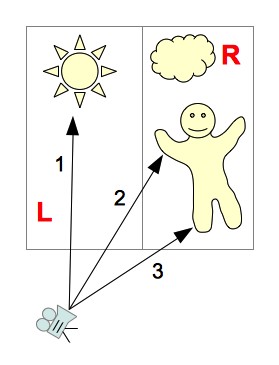
Since we divide the scene into parts parallel to the coordinate axes, we can comparatively quickly calculate which part of the panoram the ray crosses. The following options are possible:
- The beam crosses only part of the prospect L
You can non view the objects contained in part R
(in the picture - beam 1) - The beam crosses only part of the shot R
You lavatory not view the objects controlled in part L
(in the picture - beam 3) - The ray first crosses part of the scene L, and so part of the scene R
First, we take objects belonging to part of the scene L - if the intersection was ground, then objects belonging to part of fit R can not comprise viewed. If the shaft does non cross some physical object from part L - you rich person to view objects from part R
(in the delineation - beam 2) - The beam of light first crosses part of scene R, then part of scene L.
The one logic for exploratory for intersections every bit in the previous version (only first we consider part of scene R)
But, in exactly the same fashio, to reduce the number of viewed polygons - you can continue to recursively dissever the scene into smaller sections. The resulting hierarchal structure containing scene segments, with primitives attached to them, is called a kd-tree .
E.g., let's take the physical process of tracing beam 2 :

- The ray basic crosses the left section of the aspect (L), then the right - R
- From part L - the ray crosses only the LL section
- LL section contains no objects
- Go to the right half of the shot - R
- In the suitable half of the fit, the beam first crosses the RL section, and past RR
- In the RL scene, the crossway of the beam with the object was found
- Trace Complete
Repayable to the organization of the tree-like data structure, we excluded those objects that obviously do not intersect the beam. But there is still a very epochal nuance - the effectiveness of the kd-tree depends on how we offend the scene into parts. How to opt the rank to split the scene?
Surface arena heuristic
The probability that a beam of light hits a segment of the scene is proportionate to the area of that segment. The more than primitives are contained in a section of the scene, the more intersections will need to be deliberate when a irradiatio hits this section. Thus, we stool formulate a criterion for partitioning: we need to minimise the product of the enumerate of primitives and the area of the segment in which they are contained. This criterion is called Area Heuristic program (SAH):
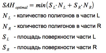
Let's take a heuristic in action using a simple good example:

Thusly, using SAH allows United States to effectively differentiate white space and 3D objects - which has a very positive set up on rendering performance.
Observations
In the interlingual rendition, the ability to calculate the intermediate number of intersections per 1 pixel of the image is implemented: all time the intersection of a ray with an object is calculated, the counter value increases, at the end of rendering, the counter prize is cloven by the number of pixels in the image.
The results obtained vary for different scenes (since the construction of the kd-tree depends on the relative position of the primitives). The graphs show the dependence of the medium number of intersections per 1 pixel of the image on the number of primitives:
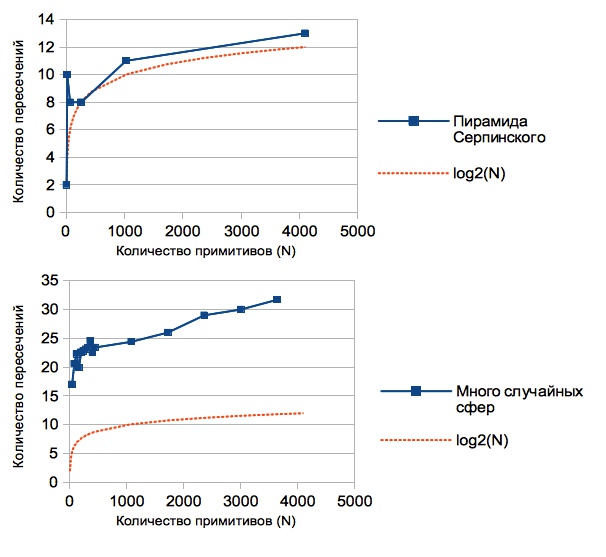
You throne card that this value is overmuch less than the number of primitives contained in the view (if there were no kd-tree, then we would have a linear dependance, because for from each one ray we would have to look for the intersection with all N primitives). In fact, using the kd-tree, we undergo reduced the complexity of the algorithm for raytracing from O (N) to O (backlog (N)).
For the sake of justice, it is Worth noting that cardinal of the disadvantages of this solution is the resource consumption of building a kd-corner. But for static scenes - this is not critical: they loaded the scene, waited for the tree to build - and you nates go traveling with the camera around the scene :-)
A scene containing 16386 triangles:
Download Models
Having learned to provide a battalion of primitives, a trust appeared to load 3D models. A fairly simple and widespread format was Chosen - OBJ : the model is stored in a text file cabinet that contains a list of vertices and a lean of polygons (each polygonal shape is outlined by points from the number of vertices).
An example of a identical simple model: tetrahedron.obj
# tetrahedron
# vertexes:
v 1.00 1.00 1.00
v 2.00 1.00 1.00
v 1.00 2.00 1.00
v 1.00 1.00 2.00
# triangles:
f 1 3 2
f 1 4 3
f 1 2 4
f 2 3 4
In the process of authorship the parser of the OBJ initialize, it was detected that many a models besides contain a inclination of normals to each vertex of the polygon. The normal vectors of the vertices buttocks be interpolated to obtain a normal transmitter at any point in the polygon - this technique allows you to simulate smooth surfaces (figure Phong shading ). This feature was quite easy to implement within the framework of the current furnish architecture (you just needed to add regular vectors to the Triangle3d body structure and write a affair that interpolates them for whatsoever repoint of the polygon).
Triangle3d structure from picture sources
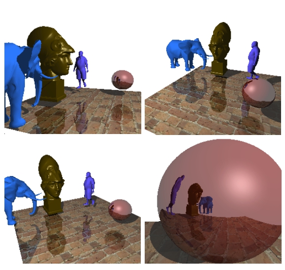
typedef struct { // координаты вершин Point3d p1; Point3d p2; Point3d p3; // вектор нормали, рассчитанный по трём вершинам // если используется затенение по Фонгу - тогда нам этот атрибут не важен Vector3d average; Color color; Material material; // если текстура отсутствует - закрашиваем триангл цветом, который указан в gloss Canvas * texture; // текстурные координаты // используем только тогда, когда есть текстура Point2d t1; Point2d t2; Point2d t3; // векторы нормали в вершинах // используем только в случае затенения по Фонгу Vector3d n1; Vector3d n2; Vector3d n3; // есть ещё несколько служебных атрибутов // которые используются для сокращения вычислений } Triangle3d; An example of a renderer scene containing about 19,000 polygons:

An example of a renderer scene containing virtually 22,000 polygons:
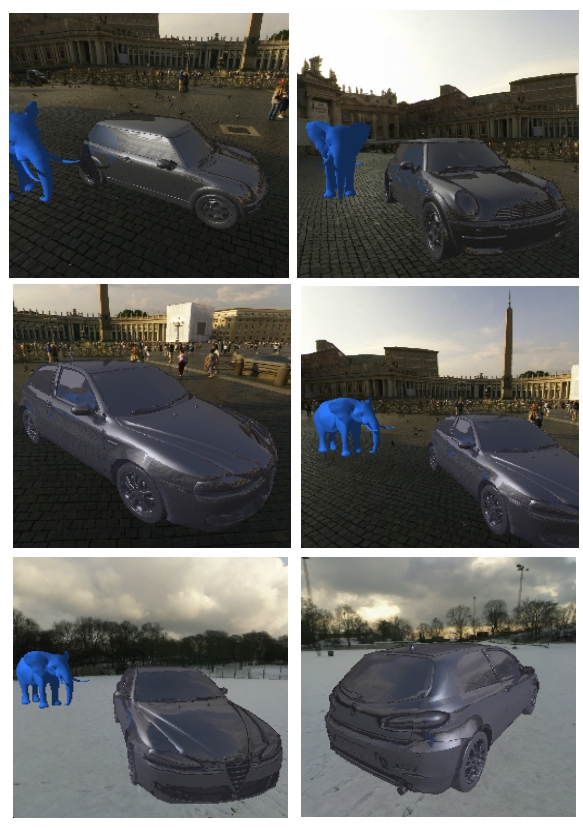
For the interest of interest, I decided to add a skybox and load car models:
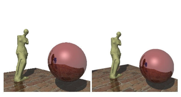
The scene contains about 100,000 polygons (a kd tree was built in few minutes)
Conclusion
I am glad that I chose this task while poring over C - because, it allowed me to watch various aspects of the spoken language ecosystem and get esthetic results.
Github render sources: github.com/lagodiuk/raytracing-render (in the project description - how to start the present).
In the process of studying, 2 books helped me a lot:
- Brian Kernighan, Dennis Ritchie - The C computer programing language - initially had some difficultness reading this book. But after recital Headway Kickoff C, I returned to this book over again. There are more examples and tasks in this book that have helped in the study.
- St. David Griffiths, Dawn Griffiths - Head Front C - I liked this book identical much because it gives a general vision of the C ecosystem (how the memory works, how it works at the OS level, stool, valgrind, POSIX streams, unit testing are described in general terms) , and there are even a a few pages about Arduino)
Also, I want to give thanks dmytrish for advice on some of the nuances of C, and for the graphical frontend for interpretation (using GLUT) - systematic to display the panoram in the window, and use the keyboard to move and revolve the camera.
I also wish to commend a very reusable resource: ray-tracing.ru - here, in an accessible form, various algorithms are used that are used for photorealistic interlingual rendition (in particular, kd-trees and SAH).
Postscript
Single videos created during the development of the render:
Sierpinski Pyramid in the Daze
Block, human beings, lantern, teapot and Sierpinski pyramid :-)
UPD:
It off out to accelerate the construction of the tree diagram. Details in the comments thread: habrahabr.ru/post/187720/#comment_6580722
UPD 2:
After discussing comments in this yarn: habrahabr.ru/post/187720/#comment_6579384 - anti-aliasing was implemented. Thanks to everyone for the ideas. Now the rendered images look prettier :)
DOWNLOAD HERE
GET Raytracing render in C / Sudo Null IT News FREE
Posted by: turnerthoonions.blogspot.com
0 Response to "GET Raytracing render in C / Sudo Null IT News FREE"
Post a Comment